
Temperature Concepts for SMD Resistors: Terminal Temperature vs. Ambient Temperature
For many years, measuring the ambient temperature was the gold standard for determining the thermal load on components, including resistors, on a PCB. This was easy to measure, as it only required placing a sensor above a PCB or inside an enclosure. Accordingly, virtually all resistor datasheets specified the “Rated Ambient Temperature”—the ambient temperature at which derating begins (see Figure 1, red line).
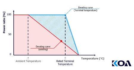
For thick-film resistors, the Rated Ambient Temperature is typically 70⁰C, while for thin-film resistors it is usually 85⁰C. Above these temperatures, the component may only be operated with progressively lower power levels.
Things Were Different in the Past
As simple and widespread as this temperature concept is, it has some significant drawbacks. Measuring the temperature somewhere above the board actually reveals relatively little about the temperature conditions at or within the individual component. For example, if the resistor is installed near a power semiconductor or a heat sink, the ambient air will certainly be heated more by these components than by the SMD component itself.
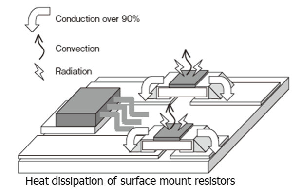
In the good old days, when THT types were predominantly used, the principle of ambient temperature may have made sense, as the body of a leaded resistor dissipates most of its heat to the ambient air. In contrast, SMD resistors dissipate over 90% of their heat to the circuit board.
Adhering to the ambient temperature concept always required applying a derating factor to the power ratings of resistors in the datasheets. Precisely because an ambient temperature of 70⁰C reveals little about the heating of the SMD resistor (whose temperature could be significantly higher), a conservative specification of the respective rated power was necessary. Consequently, larger and more expensive resistors than technically necessary tend to be used, wasting space on the circuit board.
Measuring at the Terminals
A much more meaningful measurement for SMD resistors, however, is measuring the temperature at the terminals. These measurement results provide a realistic picture of the thermal load on the resistor. Accordingly, a derating factor for the component’s rated power can be omitted. It is important to consider the temperature at the terminals from which derating begins (see Figure 1, blue line). As a result, the component can handle a higher power than when only the ambient temperature is considered. If this power is not required, a smaller package size may also be an option.
Developers occasionally point out that while they do not measure the terminal temperature, they do measure the hot spot temperature of a resistor. Even though the delta varies depending on the package size, it can be assumed that the hot spot temperature is always above the terminal temperature. Therefore, as long as the hot spot measurement does not exceed the Rated Terminal Part Temperature specified in the datasheet, you are definitely on the safe side.
KOA offers both temperature concepts in the datasheets for many series. Depending on the design requirements, the appropriate measurement approach and the suitable component can be selected.
Certainly, measuring the temperature of SMD terminations is more complex than the blanket measurement of ambient temperature. It is also important to ensure during circuit design that the board is not thermally overloaded. However, given the potential for saving space and costs, the effort appears justified.